

Frame Size, Icu/Ics and Mounting Type
Configuration Options Explained — Featuring the CJMM1 MCCB by C&J Electrical
A moulded case circuit breaker (MCCB) sits in the middle of the low-voltage switchgear range — heavier than an MCB but smaller and lighter than an air circuit breaker. It handles higher currents, can carry adjustable trip settings, and is the standard choice for main feeders, large motors and the incomer of a commercial distribution board.
Choosing an MCCB involves more than matching the rated current to the load. The frame size, breaking capacity (Icu and Ics), number of poles, type of trip unit, and mounting style all affect whether the breaker will work safely and conveniently in the installation. C&J Electrical’s CJMM1 series is one example of a single platform that covers frame sizes from 125A to 800A, M and H breaking-capacity levels, 2-pole, 3-pole and 4-pole versions, thermal-magnetic and electronic trip units, fixed/plug-in/draw-out mounting, and a rotary locking handle option — so the right configuration can be selected without changing product family.
MCCB vs MCB: Where Each Fits
An MCB (miniature circuit breaker) and an MCCB both protect circuits from overload and short circuit, but they cover different scales. An MCB is typically rated up to 125A with fixed trip settings and is the natural fit for residential and final branch circuits. An MCCB is available across a wide range of rated currents (up to about 2500A) with adjustable trip settings and higher breaking capacity, and is used for main feeders, large motors and commercial distribution. They are governed by different IEC standards: MCB by IEC 60898-1 (and IEC 60947-2 for industrial versions), MCCB by IEC 60947-2.
In a typical distribution board both devices appear together: the MCCB protects the main incomer and larger feeders, while the MCB handles the final circuits downstream. Selecting an MCCB therefore sets the performance ceiling for the whole panel.
Key Configuration Parameters of an MCCB
When selecting an MCCB, the following parameters usually determine the right configuration:
- Frame size (rated frame current) — the size of the breaker family (for example 125A, 250A, 400A, 630A or 800A). The frame size must be equal to or larger than the highest rated current (In) you expect to set.
- Number of poles — available in 2-pole, 3-pole and 4-pole configurations, depending on whether the circuit is single-phase or three-phase and whether the neutral is switched.
- Breaking capacity — the rated short-circuit breaking capacity of the breaker, expressed as Icu and Ics.
- Trip unit — thermal-magnetic for general use with a fixed characteristic, or electronic for adjustable overload, short-circuit and pre-alarm settings.
- Mounting type — fixed, plug-in or draw-out.
- Accessories — locking handle, shunt trip, undervoltage release, motor operator, rotary handle.
Breaking Capacity Explained: Icu and Ics
Icu and Ics are rated short-circuit breaking capacities that describe the fault current the breaker is designed to interrupt under standard test conditions. They differ in what the standard requires of the breaker afterwards:
- Icu — rated ultimate short-circuit breaking capacity. After clearing a fault of this magnitude under the standard test sequence, the circuit breaker is not required to continue carrying its rated current.
- Ics — rated service short-circuit breaking capacity. It is usually expressed as a percentage of Icu; after clearing a fault of this magnitude, the circuit breaker should still be able to carry its rated current and remain in service.
In practice, the rated short-circuit breaking capacity (Icu) should be checked against the prospective short-circuit current at the installation point: the Icu must be equal to or greater than the prospective fault current, and the Ics should be adequate for the expected fault duty. Many product families offer two breaking-capacity levels on the same frame size, often labelled M (the standard rating) and H (a higher rating for installations with higher available fault current), so that the same frame can be specified across different parts of the distribution network.
Mounting Types: Fixed, Plug-in and Draw-out
Mounting style affects how the breaker is installed, replaced and maintained:
- Fixed — the breaker is bolted directly to the back plate of the panel. It is the most compact and the most economical option.
- Plug-in — the breaker engages a fixed base via plug-in contacts. The body of the breaker can be removed and replaced quickly without disturbing the busbar or the incoming wiring.
- Draw-out — the breaker can be racked between the connected position, the test position and the isolated (disconnected) position on a chassis. It allows the breaker to be isolated and withdrawn for inspection without opening the busbar chamber.
Plug-in and draw-out are usually chosen where regular inspection or rapid replacement is expected, or where Lockout/Tagout procedures require the breaker to be physically removed from the circuit.
Trip Units: Thermal-magnetic vs Electronic
Thermal-magnetic trip units combine a thermal element (for delayed overload tripping) with a magnetic element (for instantaneous short-circuit tripping). They are simple, robust and sufficient for general-purpose applications. Electronic trip units use current sensors and an electronic processing circuit to measure the current directly and apply adjustable time-current characteristics. They allow the overload setting (Ir1), short-time-delay setting (Ir2), instantaneous setting (Ir3) and pre-alarm setting (Ir0) to be adjusted on the device, and they support coordination between upstream and downstream breakers.
Introducing the CJMM1 Series
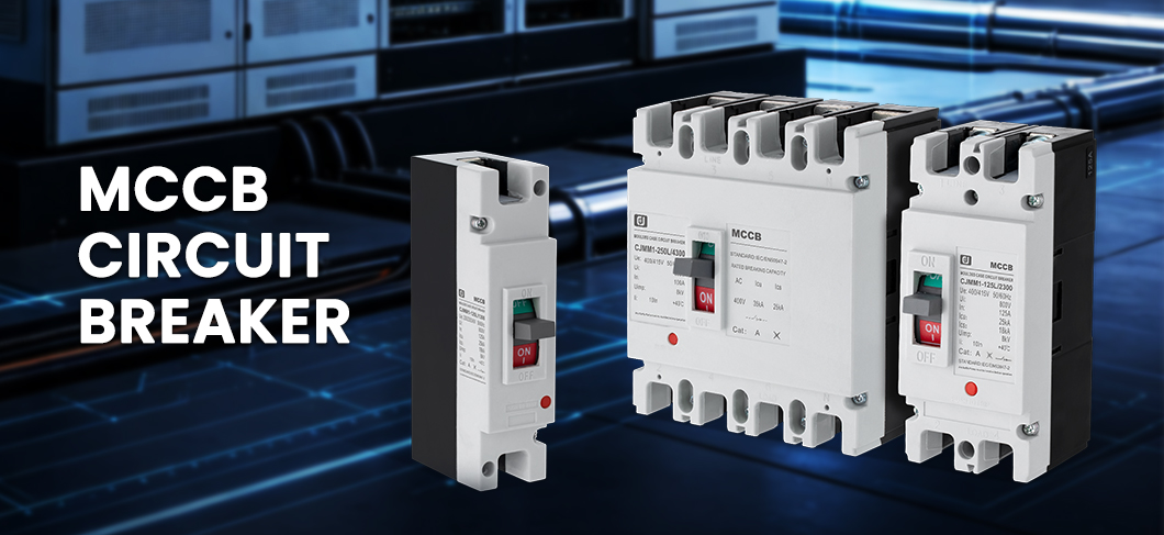
The CJMM1 series from Zhejiang C&J Electrical Co., Ltd. is an MCCB family designed to cover the configurations most commonly specified in industrial and commercial installations. The series shares a common set of accessories and the same IEC 60947-2 platform.
Key technical data of the CJMM1 series (thermal-magnetic and CJMM1E electronic versions):
| Frame size (rated frame current) | 125A, 250A, 400A, 630A, 800A |
| Number of poles | 2P, 3P, 4P |
| Rated operational voltage (Ue) | AC 400 V (up to 690 V depending on configuration) |
| Rated insulation voltage (Ui) | AC 1000 V |
| Rated impulse withstand voltage (Uimp) | 8 kV |
| Breaking-capacity levels | M (standard) and H (higher) |
| Icu / Ics at 400 V, 125A and 250A frames | M: 50 kA / 35 kA · H: 85 kA / 50 kA |
| Icu / Ics at 400 V, 400A, 630A and 800A frames | M: 65 kA / 42 kA · H: 100 kA / 65 kA |
| Utilisation category | A (125A, 250A) · B (400A, 630A, 800A) |
| Trip units | Thermal-magnetic (standard) or electronic (CJMM1E) |
| Mounting | Fixed, plug-in and draw-out options |
| Mechanical / electrical endurance | 3000 / 7000 cycles (125A, 250A) · 2000 / 4000 (400A) · 1500 / 3000 (630A, 800A) |
| Operating conditions | Ambient temperature -5°C to +40°C · altitude ≤ 2000 m |
| Standard | IEC 60947-2 |
CJMM1 Configurations at a Glance
The CJMM1 platform supports the following configurations within the same product family:
- Five frame sizes (125A, 250A, 400A, 630A, 800A) so the same installation practice, accessories and busbar interfaces can be used across the distribution network.
- Two breaking-capacity levels per frame size (M and H), so the breaker can be matched to the prospective fault current at each point in the network.
- 2-pole, 3-pole and 4-pole versions, covering single-phase and three-phase circuits and switched-neutral arrangements.
- Thermal-magnetic trip units for general applications and CJMM1E electronic trip units with adjustable overload, short-circuit and pre-alarm settings for coordinated protection.
- Fixed, plug-in and draw-out mounting options, so the breaker can be specified for compact panels, replaceable installations or maintainable systems.
- A rotary locking handle variant (CJMM1-K) for installations where the breaker must be lockable in the OFF position during maintenance.
Application Scenarios
The CJMM1 series is suited to the following installations:
- Main incoming circuit breaker in industrial and commercial distribution boards.
- Sub-distribution feeders where adjustable trip settings or higher breaking capacity are required.
- Motor feeders and motor control centres (utilisation category A on the smaller frames).
- Installations where quick replacement is expected (plug-in or draw-out mounting).
- Lockable installations such as switchrooms or maintenance areas where Lockout/Tagout procedures apply.
Does an MCCB Provide Residual Current Protection?
A common question is whether an MCCB provides residual current (earth leakage) protection. It does not: an MCCB protects against overload and short circuit, but it does not detect residual current. For residual current protection, an RCCB or RCBO is normally installed alongside the MCCB, or on the feeder it serves. The CJMM1E electronic version of the series supports residual current protection and phase-loss protection as optional functions integrated into the trip unit, which is useful where the panel space is limited.
About C&J Electrical
Zhejiang C&J Electrical Co., Ltd. is a manufacturer of low-voltage electrical products, focused on circuit breakers and related protection devices. C&J Electrical supports OEM brand customization, offers a range of specifications, and can ship products as SKD kits for local assembly.
For more information on the CJMM1 series or to request a quotation, please contact us at Wechat/Whatsapp [0086-13968744102].
Post time: Aug-27-2026