


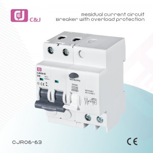
Made in China CJL16-40 AC Type 1P+N Residual Current Circuit Breaker with Overcurrent Protection RCBO
Technical Data
| Standards | IEC/EN61009-1 |
| Type | Electro-magnetic type |
| Residual current characteristics | AC A |
| Pole No. | 1P+N |
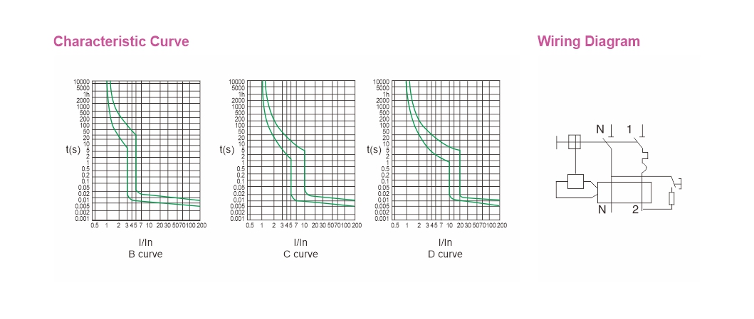
| Tripping curve | B, C, D |
| Rated short-circuit capacity | 10kA |
| Rated current (A) | 1A,2A,3A,4A,6A,10A,16A,20A,25A,32A,40A |
| Rated voltage | 240V AC |
| Rated frequency | 50/60Hz |
| Rated residual operating current(mA) | 0.03,0.1,0.3 |
| Tripping duration | instantaneous≤0.1s |
| Electro-mechanical endurance | 4000 cycles |
| Connection terminal | pillar terminal with clamp |
| Connection capacity: | Rigid conductor 16mm² |
| Terminal connection height | 21.5mm |
| Installation | On symmetrical DIN rail 35mm |
| Panel mounting | |
| Wiring Diagram |
Overload Current Protection Characteristics
| Test procedure | Type | Test Current | Initial State | Tripping or Non-tripping Time Limit | Expected Result | Remark |
| a | B,C,D | 1.13In | cold | t≥1h | No tripping | |
| b | 1.45In | after test a | t<1h | tripping | Current in the 5s in th increase of stability | |
| c | 2.55In | cold | 1s<t<60s | tripping | ||
| d | B | 3In | cold | t≥0.1s | No tripping | Turn on the auxiliary switch to close the current |
| C | 5In | |||||
| D | 10In | |||||
| e | B | 5In | cold | t<0.1s | tripping | Turn on the auxiliary switch to close the current |
| C | 10In | |||||
| D | 20In | |||||
| The terminology “cold state” refes to that no load is carried before testing at the reference setting temperature. | ||||||
Residual Current Action Breaking Time
| Type | In/A | I△n/A | Residual Current (I△) Is Corresponding To The Following Breaking Time (S) | ||||
| AC type | any value | any value | In | 2In | 5In | 5A,10A,20A,50A,100A,200A,500A | |
| A type | any value | >0.01 | 1.4In | 2.8In | 7In | ||
| 0.3 | 0.15 | 0.04 | 0.04 | Max Break-time | |||
| The general type RCBO whose current IΔn is 0.03mA or less can use 0.25A instead of 5IΔn. | |||||||
Write your message here and send it to us
Products categories
-

18mm Single Module RCBO 6KA 1P+N B&C Curve...
-

18mm Single Module RCBO 6KA 1P+N B&C Curve...
-
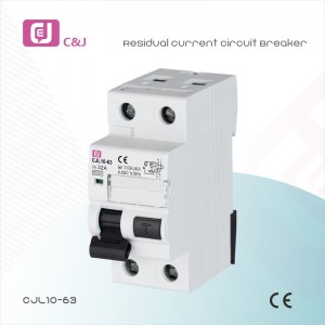
China Factory CJL10-63 2p 6ka 25-63A RCBO, MCB ...
-
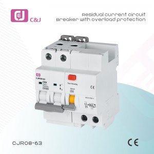
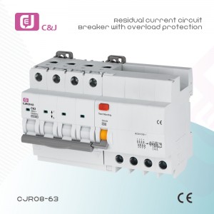
China Manufacturer CJRO8-63 2P 10kA 63A 30mA RC...
-
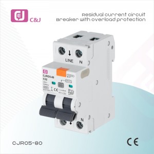
China Supplier CJRO5-80 Magnetic Type 2P 32A 6k...
-

Made in China CJL16-40 AC Type 1P+N Residual Cu...
-
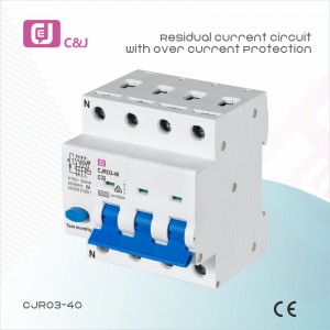
CJRO3 6-40A 3p+N RCBO Residual Current Circuit ...
-
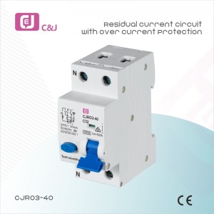
CJRO3-40 1p+N RCBO ELCB Residual Current Circui...
-
High quality CJRO8-63 4P 63A 30mA Residual RCBO...
-

Plug in Type 1p+N 6/10ka Single Phase Earth Lea...
-
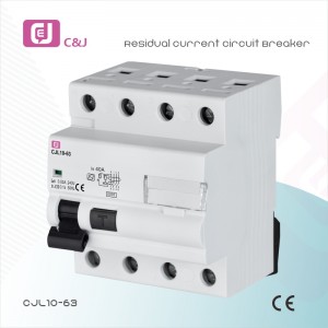
Wholesale Price CJL10-63 4p 6ka 25-63A RCBO, MC...
-

Wholesale Price CJRO5-80 4P 40A 6kA RCBO MCB RC...
-
Wholesale price CJRO6-63 2P 6-63A DIN Rail moun...